


LCD Display Interface Guide: SPI vs RGB vs MIPI vs LVDS vs HDMI
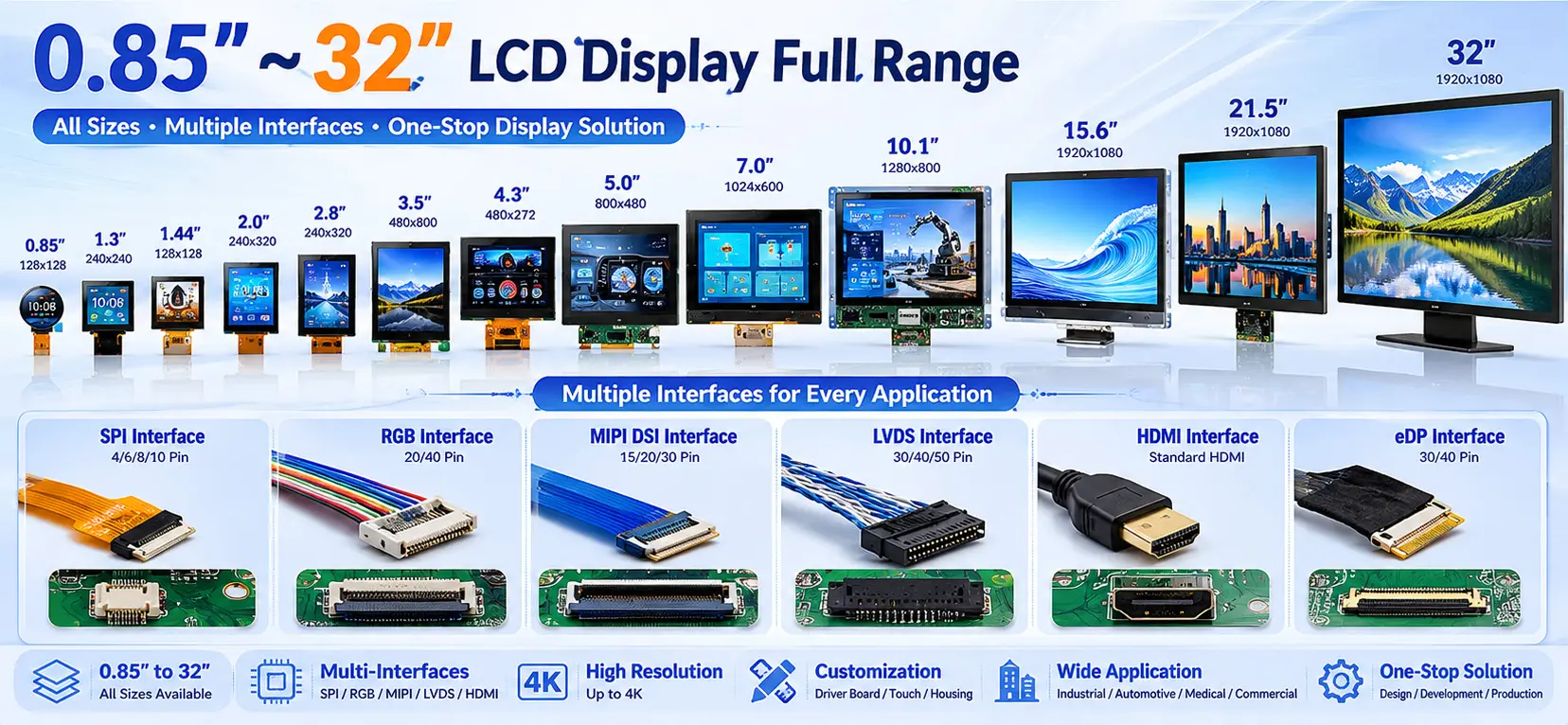
2026-05-29 16:28:042026/05/29/810632067338373.webp" style=""/>Choosing the right LCD display interface is one of the most important decisions in lcd display system design. The interface directly affects display quality, signal stability, development complexity, hardware compatibility, and overall project cost.From ultra-small 0.85-inch wearable displays to 32-inch industrial and commercial LCD panels, different display sizes, resolutions, and application environments require completely different interface solutions.In actual hardware development, engineers often encounter issues such as: LCD flickering, Screen noise or color distortion, Failed initialization, Signal interference, Long-distance transmission instability, Mainboard interface incompatibilityIn most cases, these problems are caused by selecting an unsuitable display interface.This article provides a complete comparison of the five most common LCD interfaces — SPI, RGB, MIPI DSI, LVDS, and HDMI — including working principles, technical characteristics, advantages, limitations, typical display sizes, and recommended applications.We will also explain practical interface selection strategies and introduce customized PCBA driver board and ODM solutions for interface compatibility issues.1. Mainstream LCD Display Interfaces ExplainedModern LCD modules from 0.85" to 32" mainly use five common display interfaces. Each interface is designed for specific display sizes, transmission requirements, and application scenarios.1.1 SPI InterfaceWhat Is SPI Interface?SPI (Serial Peripheral Interface) is a low-speed synchronous serial communication interface widely used in ultra-small LCD displays and embedded systems.Because of its simple wiring structure and low hardware resource consumption, SPI is one of the most cost-effective display interfaces for compact devices.SPI Interface Features: Simple serial communication, Very low pin count, Low power consumption, Easy firmware development, Low hardware costTypical SPI signals include: SCLK (Clock), MOSI (Data), CS (Chip Select), DC (Data/Command)SPI Interface Limitations: Limited transmission bandwidth, Lower refresh rate, Not suitable for high-resolution video, Long-distance transmission may cause display lag or instabilitySPI interfaces are generally limited to low-resolution displays such as: 240×240, 240×320, QVGA-level TFT LCDsRecommended Display Size: 0.85" – 2.8"Typical SPI LCD Applications: Smart watches, Wearable devices, Small medical instruments, Home appliance, control panels, IoT display modules, Portable testing equipment1.2 RGB InterfaceWhat Is RGB Interface?RGB is a parallel display interface that transfers image data through separate Red, Green, and Blue signal buses combined with synchronization signals.RGB has been widely used in industrial TFT LCDs and consumer electronics because of its mature technology, stable performance, and broad MCU compatibility.RGB Interface Features: Stable display refresh, Supports 8-bit / 16-bit / 24-bit color depth, Compatible with most MCUs and industrial controllers, Cost-effective for mass productionGB interfaces are commonly used together with: STM32 LTDC, Industrial ARM boards, Embedded Linux systemsRGB Interface Limitations: Requires many PCB signal lines, Occupies large MCU pin resources, Single-ended signals are sensitive to EMI interference, Long-distance transmission may cause flickering or image distortionIn most cases, RGB transmission distance should remain below 30 cm. Recommended Display Size: 2.4" –7"Typical RGB LCD Applications: Industrial HMI displays, Smart home control panels, Portable industrial instruments, Automotive sub-displays, Security terminals1.3 MIPI DSI Interface What Is MIPI DSI?MIPI DSI (Mobile Industry Processor Interface Display Serial Interface) is a high-speed differential serial display interface designed for modern mobile and high-resolution embedded displays.Compared with RGB interfaces, MIPI greatly reduces wiring complexity while improving signal integrity and display quality.MIPI DSI Features: High-speed differential transmission, Excellent EMI resistance, Compact FPC cable structure, Supports HD and Full HD resolution, Lower power consumption than RGB, Ideal for touch-integrated displaysMIPI DSI is currently the mainstream interface for modern high-resolution LCD modules.MIPI DSI Limitations: More complex protocol architecture, Higher firmware development difficulty, Requires compatible SoC or processor support, Low-end MCUs may not support MIPI directlyIn most cases, RGB transmission distance should remain below 30 cm. Recommended Display Size: 3.5" – 10.1"Typical MIPI Display Applications: Automotive infotainment displays, Medical devices, Smart terminals, High-resolution industrial HMIs, Consumer electronics1.4 LVDS Interface What Is LVDS?LVDS (Low Voltage Differential Signaling) is a differential transmission interface designed for high stability and long-distance signal transmission.LVDS is widely used in industrial and commercial large-size displays because of its strong anti-interference capability and stable image quality.LVDS Features: Excellent EMI resistance, Supports long-distance transmission, Stable image transmission, Supports Full HD and 2K resolution, Suitable for harsh industrial environmentsLVDS transmission distance can exceed 1 meter while maintaining stable image quality.LVDS Limitations: Higher hardware cost, Requires dedicated LVDS driver circuits, Less suitable for ultra-small displaysRecommended Display Size: 7" –32"Typical LVDS Applications: Industrial all-in-one PCs, Outdoor self-service terminals, EV charging stations, Industrial control systems, Commercial equipment, Vehicle-mounted industrial displays1.5 HDMI Interface What Is HDMI?HDMI (High-Definition Multimedia Interface) is a standardized digital multimedia interface capable of transmitting video and audio simultaneously.Because of its universal compatibility and plug-and-play capability, HDMI is widely used in commercial and large-size display systems.HDMI Features: Standardized interface, Supports Full HD and 4K resolution, Audio and video integrated transmission, Excellent compatibility, Easy system integrationHDMI is compatible with: PCs, Industrial computers, Android boards, Media systems, Embedded Linux platformsHDMI Limitations: Higher power consumption, Large connector size, Not suitable for ultra-compact embedded devicesRecommended Display Size: 15.6" – 32"Typical HDMI Applications: Advertising displays, Commercial kiosks, Industrial monitors, Embedded large-screen terminals, Home multimedia systems2. LCD Interface Comparison TableInterfaceRecommended SizeMax ResolutionEMI ResistanceTransmission DistancePower ConsumptionDevelopment DifficultyTypical ApplicationsSPI0.85"–2.8"≤320×480Medium≤10cmVery LowEasyWearables, IoTRGB2.4"–7"≤800×480Weak≤30cmMediumEasyIndustrial HMIMIPI DSI3.5"–10.1"1080PStrong≤50cmLowMediumAutomotive, MedicalLVDS7"–32"Full HD / 2KVery Strong≥1mMediumMedium-HighIndustrial SystemsHDMI15.6"–32"4KStrong≤80cmHighVery EasyCommercial Displays3. How to Choose the Right LCD Interface2026/05/29/810632287899781.webp" style=""/>Small Low-Power Devices (0.85"–2.8")SPI is the best choice for ultra-small embedded systems because of its simple wiring, low cost, and minimal power consumption.Recommended for: Wearables, Portable instruments, Smart appliance displaysStandard Industrial and Smart Home Devices (2.4"–7")RGB is ideal for cost-sensitive mass-production projects.If higher resolution, cleaner wiring, or touch integration is required, MIPI DSI is the better solution.High-Resolution Smart Devices (3.5"–10.1")MIPI DSI is strongly recommended for: Automotive displays, Medical equipment, Advanced HMI systems, Smart terminalsMIPI provides better image quality and stronger anti-interference capability than RGB.Industrial and Outdoor Equipment (7"–32")For long-distance signal transmission or harsh EMI environments, LVDS is the preferred interface.LVDS effectively reduces: Flickering, Noise, Signal distortion, Transmission instabilityCommercial Large Displays (15.6"–32")HDMI is ideal for commercial display systems requiring: Plug-and-play operation, Universal compatibility, Multimedia integrationTypical applications include: Advertising machines, Self-service kiosks, Industrial monitors4. Common LCD Interface Compatibility ChallengesIn real-world projects, interface compatibility issues are extremely common.Typical problems include: Upgrading RGB systems to MIPI displays, Long-distance RGB transmission instability, Driver board size limitations, Touch integration requirements, Custom embedded structures5. One-Stop LCD Customization SolutionsBesides supplying standard LCD modules from 0.85" to 32", Sinocrystal also provide complete hardware customization services.PCBA Driver Board DevelopmentSinocrystal support: SPI to RGB conversion, RGB to LVDS conversion, MIPI interface adaptation, HDMI driver solutions, Firmware development, Pin definition customizationDisplay Parameter CustomizationCustomizable parameters include: Brightness, Color temperature, Refresh rate, Wide-temperature operation, Outdoor readability,Mechanical & Housing CustomizationSinocrystal support: Plastic housings, Metal enclosures, Waterproof structures, Logo printing, Custom brackets, Industrial mechanical integrationODM & OEM Complete AssemblySinocrystal provide complete ODM solutions including: LCD module, Touch panel, Driver board, Mechanical structure, Complete assemblyCustomers can directly integrate finished systems into their products.6.FAQQ: Can different LCD interfaces be converted?A: Yes. Customized PCBA driver boards can convert SPI, RGB, MIPI, LVDS, and HDMI interfaces according to project requirements.Q:Why does RGB display flicker during long-distance transmission?A: RGB uses single-ended parallel signals that are sensitive to EMI interference. Transmission distances above 30 cm may cause flickering, noise, or color distortion.For long-distance applications, LVDS or MIPI interfaces are recommended.Q: Should small high-resolution displays use RGB or MIPI?A: For displays above 800×480 resolution, MIPI DSI is generally the better choice because it provides cleaner wiring, better image quality, and stronger EMI resistance.RGB remains suitable for lower-cost embedded systems.Q: Which interface is best for industrial outdoor equipment?A: LVDS is the preferred interface for industrial outdoor applications because of its excellent signal stability, vibration resistance, and anti-interference capability.7. ConclusionThere is no single “best” LCD interface. The correct interface depends on display size, resolution, signal stability requirements, transmission distance, power consumption, and hardware architecture.In general: SPI is best for ultra-small low-power displays, RGB is suitable for mainstream embedded TFT LCDs, MIPI DSI is ideal for high-resolution smart devices, LVDS is preferred for industrial and long-distance applications, HDMI is best for commercial large-screen systemsSinocrystal provide complete LCD display solutions from 0.85" to 32", including SPI, RGB, MIPI, LVDS, and HDMI interfaces, along with PCBA development, interface conversion, touch integration, and ODM/OEM customization services.If you need help selecting the right LCD interface for your project, our engineering team can provide one-on-one technical support and customized display solutions.

How Many Colors Can a TFT Display Show?
2026-05-25 08:16:08But how are these colors generated? And why do some TFT displays look more vivid and colorful than others, even when they have the same resolution and color specifications?In this article, Sinocrystal explains the science behind TFT display colors in a simple and easy-to-understand way.What Are RGB Primary Colors in a TFT Display?TFT displays create colors using the three primary colors of light:Red (R)Green (G)Blue (B) This process is called additive color mixing.Every pixel on a TFT display is made up of three tiny sub-pixels:One redOne greenOne blue By adjusting the brightness of these RGB sub-pixels, the display can generate different colors.For example:Red only → RedRed + Green → YellowRed + Green + Blue → WhiteAll off → Black This is the fundamental principle behind all TFT display colors.2026/05/25/809092870967429.jpg" style="width: 598.68px;height: 355.45px;"/>Why Can TFT Displays Show 16.7 Million Colors?The answer comes from something called color depth or bit depth.The most common TFT display uses 8-bit color depth.An 8-bit system means each RGB sub-pixel can display:So:Red has 256 brightness levelsGreen has 256 brightness levelsBlue has 256 brightness levels When these three channels combine:That equals 16.77 million colors.This is why many TFT LCD displays are advertised as supporting “16.7M colors.”What Is the Difference Between 6-Bit, 8-Bit, and 10-Bit Displays?Different displays use different color depths.6-Bit DisplayCommon in entry-level or low-cost displays:Approximately 262 thousand colors8-Bit DisplayThe most common TFT display solution:16.77 million colorsSmooth color transitionsSuitable for most consumer electronics 10-Bit DisplayUsed in professional monitors and high-end applications:Approximately 1.07 billion colorsHigher bit depth provides:Smoother gradientsBetter color transitionReduced color bandingWhy Do Some TFT Displays Look Better Than Others?Even if two TFT displays both support 16.7 million colors, their actual visual performance may still look very different.This is because display quality depends on more than just color quantity.What Is Color Gamut?Color gamut refers to the range of colors a display can reproduce.A wider color gamut means:More vivid colorsHigher saturationMore realistic images For example:Standard displays may only cover part of the sRGB color spaceHigh-end displays can achieve nearly 100% DCI-P3 coverage The color gamut of a TFT display mainly depends on the purity of the RGB light wavelengths generated by the display system.2026/05/25/809092780261509.jpg" style="width: 617.36px;height: 362.93px;"/>How Backlight Quality Affects TFT Display ColorsUnlike OLED displays, TFT LCD panels do not emit light directly.Instead, they rely on a backlight module.The liquid crystal layer controls how much backlight passes through each pixel to create images and colors.Because of this, backlight quality strongly affects:BrightnessContrastColor accuracyColor purity If the backlight spectrum is not pure enough, colors may appear washed out or inaccurate.This is why premium TFT displays often use:High-quality LED backlightsQuantum Dot (QLED) technologyHigher contrast liquid crystal materials These technologies help improve overall TFT display color performance.Why Do TFT Displays From Different Manufacturers Look Different?Even with the same display size and resolution, TFT displays from different manufacturers can vary significantly in:Color performanceContrastViewing experiencePrice This is because the final display quality depends on the complete display solution, including:LCD materialsBacklight designColor calibrationDriver IC performanceManufacturing process At Sinocrystal, we focus on optimizing the complete TFT display solution to achieve better color performance and visual quality for different applications.ConclusionSo, how many colors can a TFT display show?Mathematically, a standard 8-bit TFT display can reproduce 16.77 million colors through RGB color mixing.But in real applications, display quality is also influenced by:Color gamutBacklight qualityContrast ratioLCD material performance That is why two displays with the same specifications can still look very different.Understanding TFT display colors helps engineers, product designers, and buyers choose the right display solution for their projects.

How Cleaning Processes Affect Display Reliability
2026-05-09 09:03:42Anyone familiar with display manufacturing knows that the biggest enemies of production are dust and contamination. A tiny particle can turn an entire panel into scrap. So how do manufacturers keep materials clean throughout production? What exactly is being cleaned? And how does cleaning influence reliability?In this article, we explain it clearly.1. What Are We Cleaning?1.1 What Contaminants Can Be Present?Display panels are primarily manufactured in cleanrooms. During production, transportation, storage, and loading onto production lines, panels may come into contact with different contamination sources.(1) Dust and Airborne ParticlesDust particles are constantly suspended in the air around us. This is why display production must take place in cleanrooms, where contamination is continuously controlled.A cleanroom operates around three core principles:• Isolation • Cleaning • Filtration These systems work together to minimize airborne particles and maintain a stable manufacturing environment.(2) Human ContactAlthough modern production lines are highly automated, operators are still involved in material loading, setup, and equipment adjustments.During these steps, accidental contact may occur, introducing contaminants such as:• Skin oils • Sweat • Fingerprints Even trace amounts can affect bonding quality and optical performance.(3) Contamination from Other MaterialsOther production materials can also transfer residues.For example, trays used for panel transport are often thermoformed using molds. During molding, release agents may be applied to help separate the tray from the mold. Residual release agents can transfer onto the panel surface if not properly controlled.2. How Is It Cleaned?Different contaminants require different cleaning methods.2.1 Removing DustFirst, the production environment itself must remain clean. Otherwise, particles can immediately reattach after cleaning.Large particles are typically removed using:• Cleanroom-grade wipes • Anti-static cleaning cloths This helps eliminate visible dust and loose contamination.2.2 Removing Oils, Residues, and Organic ContaminantsDry wiping alone is not enough to remove oils or chemical residues.Organic solvents are used to dissolve and lift contaminants from the surface. These solvents are applied with lint-free wipes.To avoid introducing new contamination, only high-purity analytical-grade solvents or better should be used.However, even these methods alone are not enough to maximize display bonding reliability.Why?Because when two materials are bonded together, factors such as weak boundary layers and van der Waals forces become critical.2.3 Weak Boundary Layers and Surface ForcesWeak Boundary LayerA weak boundary layer is a thin low-strength region at the bonding interface caused by:• Residual contaminants • Unreacted low-molecular compounds • Additive migration • Surface degradation This weak layer often becomes the first point of failure in an adhesive or bonding system.Van der Waals ForcesVan der Waals forces are weak intermolecular attractions that exist between molecules and atoms. While individually small, they play an important role in surface adhesion and bonding performance.To improve display bonding reliability, manufacturers must:• Remove weak boundary layers • Increase surface energy • Strengthen intermolecular attraction The most effective method to achieve all three goals is plasma treatment.2.4 What Is Plasma?We commonly know matter in three states:• Solid • Liquid • Gas When sufficient energy is applied to a gas, the gas becomes ionized into a highly active mixture of:• Electrons • Ions • Free radicals • Excited molecules • UV radiation This energized state is called plasma, often referred to as the fourth state of matter.Although highly reactive, plasma treatment can operate near room temperature, making it ideal for delicate display materials.2.5 How Plasma Cleaning WorksDuring plasma cleaning, energetic ions and reactive species bombard the material surface and remove:• Oils • Mold release agents • Low-molecular organic residues • Oxide layers • Weak boundary layers At the same time, plasma treatment introduces polar functional groups such as:• Hydroxyl groups (-OH) • Carboxyl groups (-COOH) These groups increase surface energy and improve adhesion.In hydrophilic bonding applications, activated hydroxyl groups can interact with water molecules to form hydrogen-bond networks, which may later convert into stronger covalent bonds.In addition, plasma micro-etching creates microscopic anchor points that increase real contact area and enhance:• Mechanical interlocking • Van der Waals attraction This is why plasma cleaning is a key process step in high-reliability display manufacturing.3. How Does It Affect Reliability?What happens if cleaning is insufficient?Display bonding processes require extremely high precision. Even microscopic particles invisible to the naked eye can interfere with fine IC circuits and bonding lines.Without proper removal of weak boundary layers and sufficient surface activation, displays may suffer from:• Reduced bonding strength • Shortened service life • Early failure • Delamination • Signal issues • Reliability instability By combining strict cleanroom control, solvent cleaning, and plasma treatment, overall bonding reliability can be significantly improved.Understanding the Science, Mastering the ProcessAt Sinocrystal Technology Co., Ltd., we specialize in display R&D and manufacturing with a strong focus on stability, consistency, and reliability.Display Experts — Stable and Reliable.

In-Cell vs On-Cell vs OGS: Understanding LCD Capacitive Touch Technologies
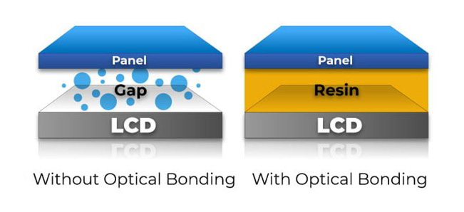
2026-04-03 09:16:53For anyone familiar with TFT LCD touch displays, the terms In-Cell, On-Cell, and OGS (One Glass Solution) are commonly encountered. These technologies represent different approaches to integrating touch functionality into LCD modules.Capacitive touch screens are widely used across various industries today. However, most conventional LCD touch displays are still separated structures, where the touch panel and LCD are manufactured independently and later assembled together.In an era driven by smarter, thinner, and more integrated devices, this traditional structure is gradually becoming insufficient to meet modern application demands.Basic Structure of LCD Touch ScreensA typical LCD touch display consists of three main layers:Cover Lens (Protection Layer) Touch Sensor Layer Display Panel (LCD Layer)In conventional designs, these layers are assembled using air bonding, which leaves an air gap between the touch panel and the LCD.2026/04/03/790708340486277.webp" style=""/>Air Bonding vs Optical BondingFull Lamination (Optical Bonding)Optical Bonding eliminates the air gap by bonding the display and touch panel using optical adhesive (such as OCA or LOCA).Advantages:Thinner and lighter structure Improved display clarity and contrast Reduced reflection and glare Better visibility under strong sunlight Dust-free internal structure Challenges:More complex manufacturing process Lower yield rate Higher cost Despite these challenges, full lamination is widely recognized as the future trend for high-end and smart display applications.Air BondingAir bonding, also known as tape bonding, uses double-sided adhesive to fix the touch panel to the LCD along the edges.Advantages:Simple process Lower cost Higher yield Limitations:Air gap between layers Increased thickness Prone to dust ingress Reduced optical performance due to light refractionCapacitive Touch Technologies: OGS vs On-Cell vs In-Cell2026/04/03/790708448755845.webp" style=""/>OGS (One Glass Solution)OGS integrates the touch sensor layer and cover glass into a single piece by depositing an ITO (Indium Tin Oxide) conductive layer directly onto the inner surface of the cover glass.Advantages:Reduced thickness (one less glass layer) Lower overall cost compared to traditional structures Widely used in full lamination solutions Limitations:Complex manufacturing process (strengthening → coating → etching → cutting) Cutting strengthened glass may create micro-cracks Potential reduction in glass strengthIn-Cell TechnologyIn-Cell technology integrates the touch function directly into the LCD pixel structure. The touch sensors are embedded within the display panel itself.Advantages:Ultra-thin design (no separate touch layer) Higher touch accuracy No parallax effect Improved sunlight readability Limitations:Highly complex manufacturing Higher cost More difficult to repair In-Cell represents one of the most advanced integration solutions in the display industry.On-Cell TechnologyOn-Cell places the touch sensor between the color filter substrate and the polarizer layer of the LCD panel.Advantages:Simpler than In-Cell Better integration than traditional external touch panels Limitations:Still faces challenges in ultra-thin design Potential issues such as uneven color during touch Less mature compared to other solutions On-Cell technology is commonly used in certain AMOLED and LCD applications.ConclusionAs display technologies continue to evolve, the demand for thinner, lighter, and higher-performance touch displays is accelerating.OGS offers a balanced solution between cost and performance On-Cell provides moderate integration with manageable complexity In-Cell delivers the highest level of integration and display performance Combined with full lamination technology, these solutions are driving the next generation of LCD touch displays toward greater optical performance and seamless user experience.

A Discussion on Main Bonding Time, Temperature, and Pressure
2026-03-19 13:41:16Anyone familiar with display modules knows that bonding is one of the most critical processes, and within it, main bonding plays a decisive role. It is no exaggeration to say that COG (Chip-on-Glass) main bonding is a “one-shot deal.”Main bonding refers to the process where the aligned IC and glass substrate are permanently joined during COG assembly. Once the bonding head comes down, everything that happens in those few seconds—the curing of ACF adhesive, the compression of conductive particles, and the formation of electrical connections—essentially determines the final result. If something goes wrong, rework is not only difficult but also highly risky, often leading to scrap.When tuning process parameters, many engineers tend to focus on whether the temperature is high enough or the pressure is sufficient, while overlooking what seems like a passive parameter: time. In fact, among the “golden triangle” of time, temperature, and pressure, time is the key variable that governs the pace of the chemical reaction.Think of it like cooking: no matter how strong the heat or how good the pot is, if the cooking time is off, the dish will either be undercooked or overdone.1.The Essence of Time: Giving the Adhesive a Chance to CureThe “curing window” specified in datasheets is essentially the optimal range for the adhesive to properly react.The core logic of setting bonding time is to match the physical and chemical changes of the ACF adhesive. Within these few seconds, two things must happen:The adhesive softens under heat, allowing conductive particles to settle properly between the IC bumps and the glass electrodes.The resin undergoes cross-linking and hardens, firmly anchoring the IC to the glass. If the bonding time is too short, the reaction inside the adhesive remains incomplete—this is what we call “undercured.” In such cases, the adhesive remains soft and lacks sufficient holding strength. Although initial functional tests may pass, this is often misleading. Over time, especially under thermal aging or field use, the adhesive may shrink, causing the IC to lift or detach—essentially a “time bomb.” On the other hand, excessive bonding time leads to “overcuring.” Over-crosslinking can make the epoxy brittle. Prolonged exposure to high temperature and pressure may also damage the ITO electrodes on the glass or weaken the sealing materials around the panel, potentially causing leakage. These hidden defects are particularly dangerous, as they may only surface during drop tests or long-term reliability testing.2026/03/19/785484427387013.png" style=""/>2. The Seesaw Relationship Between Time and Temperature In production, time and temperature are inseparable and typically compensate for each other. Adjusting one often requires adjusting the other.2026/03/19/785484509356165.jpg" style=""/>(1) High Temperature, Short Time: Higher Throughput, Higher RiskTo increase production capacity (UPH), a common approach is to raise the temperature and reduce bonding time—for example, shortening a 10-second process to 5 seconds. While theoretically feasible, this approach carries significant risk. Heat transfer takes time. If the bonding head temperature is too high while the duration is too short, the surface of the ACF may overheat or even carbonize, while the interior remains insufficiently cured. This “burnt outside, raw inside” condition leads to poor bonding strength. Unless your equipment offers extremely fast and stable thermal response, operating at such limits is not recommended.2026/03/19/785484831514757.png" style=""/>(2) Low Temperature, Long Time: Stability Over EfficiencyWhen dealing with heat-sensitive components or limited heating capability, extending bonding time is often the safer option. Although this reduces throughput, it ensures uniform curing throughout the adhesive.Experience shows that it is better to add a few extra seconds to secure quality than to push the limits for marginal gains in cycle time. The cost of rework or customer complaints far outweighs the benefit of saving a few seconds. 3. Pressure: The Most Misunderstood FactorPressure is often overemphasized in bonding processes. Many assume that higher pressure is always better—but this is a misconception. The primary role of pressure is to bring the IC and glass into close contact, allowing conductive particles to embed into the electrodes:If the pressure is too low, particles cannot make proper contact, resulting in open circuits.If the pressure is too high, particles may be crushed or the electrodes themselves may be damaged. The relationship between pressure and time is more about coordination:With proper pressure, bonding time only needs to ensure sufficient curing.If pressure is excessive, the process becomes more sensitive to time. Prolonged high pressure can accelerate electrode fatigue or even crack the glass. If you find bonding time difficult to optimize, it may be worth revisiting whether the pressure setting is too high. 4. How to Verify Whether the Bonding Time Is Appropriate Setting parameters is not enough—verification is essential. (1) Shear Test: Where Does It Fail?Using a force gauge to push the IC, it is important not only to check the force value but also to examine the failure mode: Acceptable: Failure occurs within the adhesive (cohesive failure), indicating proper curing and sufficient bonding strength.Unacceptable: The IC cleanly detaches from the glass (interfacial failure), suggesting insufficient curing time. (2) Microscopic Inspection: How Are the Particles Deformed?Under a microscope, conductive particles should appear compressed into an elliptical shape, making firm contact with both electrodes:If particles remain spherical, it indicates insufficient pressure or incomplete adhesive softening (time/temperature too low).If particles are crushed, it suggests excessive pressure or over-compression due to prolonged bonding. Conclusion There is no absolute “correct answer” in main bonding—only the most suitable balance for a given scenario. Process optimization is essentially about making trade-offs between time, temperature, and pressure. Engineers must understand that ACF curing is driven by energy—specifically, the integration of temperature over time—while pressure ensures proper particle contact. Among these three factors, time is often the most compromised (for the sake of throughput), yet also the most critical to reliability. Without sufficient validation and confidence, it is wise to protect the lower limit of the process window rather than blindly pushing for maximum efficiency. After all, for customers, reliability and low defect rates are far more valuable than saving a few seconds in production.

Fundamental Display Solutions by Sinocrystal
2025-11-28 09:59:25Building a Display From the Ground Up: Sinocrystal’s Core Display SolutionsInside every device equipped with a screen, the display system is usually composed of three essential parts: the display panel that presents visual content, the touch layer enabling interaction, and the driver board with housing that powers and supports both.This article focuses on the core of all screens: the base display module, also known as the “bare display,” and provides a deeper look into Sinocrystal’s expertise in this field.1. The “Simple” Bare DisplayA compact display may look straightforward, yet it is an intricately engineered module. Structurally, it consists of three critical elements: the panel, the driver, and the connection interface. Understanding how these components work together is the first step in selecting the right display solution.2025/11/28/746131683635333.webp" style="width: 50%;"/>2. The Core Component: The PanelWhen designing a new product, its visual requirements define your starting point. Will a monochrome display suffice, or do you need full-color visuals?Mainstream displays can be categorized as follows:Monochrome displays: segment displays and character dot-matrix displaysColor displays: primarily TFT (Thin Film Transistor) and OLED (Organic Light-Emitting Diode)Segment LCD TFT LCD2025/11/28/746131914678405.jpg" style="width: 100%;"/>2025/11/28/746131961368709.jpg" style=""/>Mono graphic lcdOLED Display2025/11/28/746132000342149.jpg" style=""/>2025/11/28/746132032946309.jpg" style=""/>2.1. Pros and Cons of Four Common Display TypesTypeAdvantagesDisadvantagesSegment display• Extremely low cost• Simple driving, very low power consumption • High contrast, wide viewing angles• Fixed display content • Cannot show complex graphics • Low flexibilityCharacter dot-matrix display• Capable of showing alphanumeric characters and symbols • Low cost, mature technology • Built-in character libraries for easy development• Low resolution • Not suitable for detailed graphics • Limited display capabilityTFT display• Full-color, vivid images • High resolution, supports video and complex UI • Mature technology and supply chain• Requires backlight, leading to higher thickness and power use • Lower contrast and response time compared to OLEDOLED display• Self-emissive, no backlight needed • Ultra-high contrast and fast response • Thinner, lighter, supports flexible designs• Higher cost • Shorter lifespan • Lower brightness compared to TFT2.2. Typical Application ScenariosSegment displays: microwaves, AC remotes, digital multimeters, metersCharacter dot-matrix displays: industrial dashboards, POS terminals, printer panels, server status monitorsTFT displays: smartphones, tablets, automotive consoles, medical monitors, smart home panelsOLED displays: premium smartphones, smartwatches, VR/AR devices, high-end TVs 2.3. Cost ComparisonIn general manufacturing scale, cost trends typically follow:Segment < Dot-matrix < TFT < OLED(However, due to higher production volume of color displays, TFTs may sometimes cost less than certain monochrome modules.)These cost differences stem from material selection, manufacturing complexity and yield rate. Sinocrystal can help balance your budget and performance needs for optimal panel selection.3. The Command Center: Driver ICIf the panel is the stage, the driver IC is the director controlling every pixel. Each panel works with a specific driver IC, determined by interface protocols such as I2C, SPI or RGB. Depending on the IC packaging method, three main technologies are used: COB, COG and COF.3.1. COB (Chip on Board): Robust and TraditionalThe IC is mounted directly onto a PCB using conductive adhesive or solder, bonded with wires, then sealed with epoxy.Advantages: Highly reliable; excellent vibration/shock resistance; cost-effective; mature technologyDisadvantages: Larger size; unsuitable for ultra-thin products; limited pin densityApplications: Industrial controllers, defense electronics, appliances with generous space and sensitivity to cost2025/11/28/746132269928581.jpg" style=""/>2025/11/28/746132341760133.jpg" style=""/>3.2. COG (Chip on Glass): Compact and MainstreamUsing ACF bonding, the IC is directly mounted on the glass substrate of the LCD. This is the most common method for small- and medium-sized displays.Advantages: Thin profile; short connection path for stable signals; highly cost-efficientDisadvantages: Requires precise manufacturing and cleanroom conditions; difficult to repairApplications: Most TFT displays, character dot-matrix screens, and some segment displays used in phones, instruments and handheld devices2025/11/28/746132437913733.jpg" style="width: 30%;"/>2025/11/28/746132471836805.jpg" style="width: 30%;"/>3.3. COF (Chip on Film): High-End and Ultra-FlexibleThe IC is mounted on a flexible printed circuit (FPC) and then connected to the panel.Advantages: Enables ultra-narrow bezels; flexible structure enhances durability; extremely high wiring densityDisadvantages: Highest cost; complex manufacturingApplications: High-end smartphones, tablets, foldable devices and wearables2025/11/28/746132541866117.jpg" style=""/>4. Communication Path: Connection MethodsThe connection method bridges the display module and the main board. The main types include metal pins, zebra strips and FPC.1. Metal PinsA classic pin-header connection, either inserted into a socket or soldered.Features: Strong, reliable, low-cost, easy for manual debuggingUse cases: Industrial displays, character modules, prototyping2025/11/28/746132633153669.jpg" style=""/>2. Zebra StripA pressure-contact connector made of anisotropic conductive rubber.Features: No soldering required; absorbs tolerance variations; moderate costUse cases: Calculators, electronic dictionaries, budget appliances2025/11/28/746132677623941.jpg" style=""/>3. FPC (Flexible Printed Circuit)One end is bonded to the panel using ACF; the other connects through a ZIF/LIF connector.Features: High connection density; bendable; space-efficient; ideal for automationUse cases: Modern high-performance electronics; standard for TFT and OLED2025/11/28/746132723159173.jpg" style=""/>5. ConclusionFrom choosing the right panel to selecting the proper driver IC and connection method, every decision shapes the performance, cost and reliability of the final display product. With years of industry experience, Sinocrystal not only ensures high production quality but also provides end-to-end solutions tailored to specific application needs.There is no single perfect technology, only the technology best suited to your product. Sinocrystal will continue to refine its capabilities and offer diverse, high-quality display solutions across industries, working together with partners to create exceptional visual experiences for the future.
LCD Bonding Technologies Explained: Optical Bonding vs Air Bonding
2025-11-14 11:13:31When it comes to LCD display integration, bonding technology plays a critical role in determining display clarity, durability, and performance. The two most common bonding methods used today are Optical Bonding and Air Bonding. Each approach has its advantages and disadvantages, and the right choice depends on your product’s application, budget, and environmental requirements.In this article, we’ll explore the key differences between optical bonding and air bonding, helping you make an informed decision for your display solution.2025/11/14/741194565275781.jpg" style=""/>2025/11/14/741194634264709.jpg" style=""/>What Is Optical Bonding?Optical bonding is a process where the cover glass or touch panel is laminated directly to the LCD module using a transparent adhesive—usually OCA (Optically Clear Adhesive) or OCR (Optically Clear Resin). This eliminates the air gap between the layers and creates a solid, optically clear structure.✅ Key Benefits of Optical Bonding:Improved display clarity: No air gap means reduced internal reflections and higher contrast.Better sunlight readability: Ideal for outdoor or high-brightness environments.Enhanced durability: The bonded structure is more shock- and vibration-resistant.Dust and moisture resistance: Sealed design prevents ingress of particles and condensation.❌ Limitations:Higher manufacturing costs.Repairs are more difficult; the entire screen may need replacement if damaged.2025/11/14/741194731450501.jpg" style=""/>What Is Air Bonding?Air bonding, also known as perimeter bonding, involves attaching the touch panel or cover glass to the LCD only around the edges, leaving a thin layer of air between them. This method is simpler and more cost-effective, commonly used in consumer electronics.✅ Key Benefits of Air Bonding:Lower cost: Less complex process, suitable for cost-sensitive projects.Easier maintenance: Easier to replace individual components (e.g., touch panel or LCD).❌ Limitations:Lower optical performance due to internal reflections.More prone to dust, fog, and moisture entering the display.Weaker structural integrity; not ideal for rugged environments. Comparison Table: Optical Bonding vs Air BondingFeatureOptical BondingAir BondingDisplay clarity⭐⭐⭐⭐⭐⭐⭐Reflection controlExcellentModerateSunlight readabilityHighLowDust and moisture resistanceStrongWeakShock and vibration resistanceStrongModerateCostHigherLowerMaintenanceMore difficultEasierIdeal applicationsIndustrial, automotive, medical, militaryConsumer electronics, office equipmentUse Case Recommendations🟦 Optical Bonding is Ideal For:Outdoor displaysAutomotive dashboard screensMedical equipmentIndustrial handheld devicesMilitary-grade displays🟩 Air Bonding is Suitable For:Tablets and smartphonesPOS terminalsSmart home devicesEducation and office displaysConclusion: Which Bonding Method Is Right for You?Choosing between optical bonding and air bonding depends on your specific needs:For high-performance, rugged, and outdoor environments, optical bonding offers superior visibility and protection.For cost-effective, indoor, or general consumer products, air bonding is a practical choice.At Sinocrystal, we offer customized LCD bonding solutions tailored to your project’s requirements. Whether you need enhanced optical performance or budget-friendly integration, our engineering team can help you select and implement the best bonding solution for your product.

What Is a Sunlight-Readable LCD and How to Choose One
2025-10-15 14:28:422025/10/15/730618192523397.webp" style="width: 638.94px;height: 399.69px;"/>What Is a Sunlight-Readable LCD Display?A sunlight-readable LCD Display is a display specially designed to remain clear and visible even under direct sunlight or bright outdoor environments. Traditional LCD screens often appear washed out or unreadable in sunlight due to screen glare and insufficient brightness. Sunlight-readable displays overcome this by using technologies such as:• High Brightness Backlight (≥1000 nits): Ensures that the screen’s luminance is stronger than ambient sunlight.• Transflective Technology: Combines reflective and transmissive properties to use natural sunlight for visibility without draining extra power.• Optical Bonding & Anti-Glare Coating: Reduces internal reflection and surface glare, improving contrast outdoors.These features make sunlight-readable LCDs essential for industrial equipment, marine displays, outdoor kiosks, automotive dashboards, and portable devices.Why Do You Need a Sunlight-Readable LCD?• Better Outdoor Visibility: Clear and sharp images under direct sunlight.• Improved User Experience: Easy to read without eye strain.• Reliable Performance: Works in challenging environments such as high temperatures or outdoor conditions.• Energy Efficiency: Some technologies (like transflective LCDs) lower power consumption by using ambient light.How to Choose the Right Sunlight-Readable LCDWhen selecting a sunlight-readable lcd display, consider the following factors:1. Brightness(Nits):For outdoor use, look for at least 800–1500 nits brightness. Industrial or marine applications may require 1000 nits or higher.2. Technology Type:• High Brightness LCDs: Suitable for kiosks, ATMs, and outdoor advertising.• Transflective LCDs: Ideal for portable devices, wearables, and applications where power saving is important.3. Surface Treatment:Choose anti-glare or anti-reflective coatings for reduced screen reflections.4. Durability:For harsh environments, ensure the display is temperature resistant, waterproof (IP65+), and vibration-proof.5. Power Consumption:Balance brightness with energy efficiency, especially for battery-powered devices.6. TouchOptions:If touch is required, consider glove-compatible or sunlight-readable touchscreensConclusionA sunlight-readable LCD is the key to delivering clear, sharp, and reliable performance in outdoor or bright-light environments. When choosing one, focus on brightness level, display technology, durability, and efficiency based on your application.By selecting the right sunlight-readable LCD, you can ensure better visibility, improved user experience, and long-term reliability for your product.

Driving LCDs with Arduino: Resolution & Interface Limitations
2025-09-15 18:27:11Driving LCDs with Arduino: Resolution & Interface LimitationsArduino is one of the most popular microcontroller development boards for makers and embedded engineers. However, due to its limited resources (especially on 8-bit boards like Arduino UNO/MEGA), the choice of displays that can be directly driven is restricted in both resolution and interface type.In this article, Sinocrystal break down the most common display interfaces for Arduino, typical resolutions they can handle, and provide a reference table of display models + Arduino compatibility + recommended MCUs. Common Display Interfaces on ArduinoParallel Interface (8/16-bit) Typical drivers: ILI9341, ST7789, SSD1963 ✅ Pros: High transfer speed, supports larger resolution ❌ Cons: Uses many GPIO pins2. SPI (Serial Peripheral Interface) Typical drivers: ST7735, ILI9341, ST7789 ✅ Pros: Simple wiring (4–5 pins) ❌ Cons: Lower bandwidth, practical for small displays3. I²C (Two-wire serial bus) Typical drivers: SSD1306 (OLED), SH1106 ✅ Pros: Only two pins (SDA, SCL) ❌ Cons: Very limited bandwidth, only small monochrome or OLED screens4. RGB / 8080 / 6800 Parallel Bus Typical drivers: SSD1963, RA8875 ✅ Pros: Supports larger TFT panels ❌ Cons: Requires faster MCU (Arduino Due, ESP32, STM32); UNO/MEGA struggle5. Special Interfaces VGA: Possible via third-party libraries at 320×240, low color depth HDMI: Not realistic on Arduino UNO/MEGA; requires FPGA or Raspberry Pi Typical Resolutions SupportedI²C OLED 128×32, 128×64 (0.96" OLED)SPI TFT 128×160 (ST7735) 240×240 (ST7789) 240×320 (ILI9341 — works on UNO, but slow)Parallel TFT 320×480 (ILI9486 / SSD1963 — better with MEGA/Due/ESP32) 480×800 (SSD1963 with external RAM — needs ESP32/STM32)High Resolution (>800×480) Beyond Arduino UNO/MEGA capability Recommended: ARM-based MCU, ESP32, STM32, Raspberry Pi, or FPGAQuick Reference TableDisplay ModelResolutionInterfaceCan Arduino UNO/MEGA Drive?Recommended MCUSSD1306 (OLED)128×64I²C✅ YesUNO / MEGAST7735128×160SPI✅ YesUNO / MEGAST7789240×240SPI✅ Yes (slow)MEGA / ESP32ILI9341240×320SPI / 8-bit Parallel⚠️ Works but slowDue / ESP32ILI9486320×4808-bit Parallel❌ Too slow on UNOESP32 / STM32SSD1963480×800RGB / Parallel❌ Not feasible on UNO/MEGASTM32 / ESP32RA8875800×480+RGB / Parallel❌ Not feasibleSTM32 / ARM Cortex-MHDMI Display≥720pHDMI❌ ImpossibleRaspberry Pi / FPGA SummaryArduino UNO/MEGA → Suitable for I²C OLED (128×64) or SPI TFT (up to 240×320).Arduino Due / ESP32 / STM32 → Capable of handling larger TFT displays (320×480 or 480×800).High-resolution panels (>800×480) → Require much more powerful hardware (e.g., Raspberry Pi, Linux SBC, or FPGA).At Sinocrystal, we specialize in LCD display solutions for embedded applications. If your project requires professional display integration, whether small OLEDs or high-resolution TFTs, our engineering team can help you select the right panel and optimize it for your MCU or system.
